Contact us...
Download...
M-SAFESWITCH-2 clean routing switch


What is it?


Dual channel IP/SDI 2 x 1 fail-safe routing switch app.
Reason to choose it...
You'll get no disruption to the output picture when a switch takes place. It will correct for any timing difference between the two inputs, thanks to the framestore synchronisers plus the ability to delay the earliest arriving input by up to ten frames – with another 60 frames available for those longer delays. You can select from ten fault conditions to automatically trigger a switch, or you can switch it manually. The fact you can use it with IP, SDI or both makes it perfect for any installation – including giving you the easiest upgrade to IP. It's dual channel to save you money. Plus it's future-proof – when this functionality is no longer required you can get a different app for your MARBLE-V1 hardware.
Ideal for...
You need a switch you can rely on to always give you a disruption-free output in your IP or SDI installation – whether for your planned maintenance switches, or as a very sophisticated auto changeover switch where you want to specify the fault conditions that will auto-trigger the switch.
Control it...
Try out the M-SAFESWITCH-2 VisionWeb GUI (opens in new window) – you'll see how easy it is to operate the M-SAFESWITCH-2 app from your web browser, while exploring the full functionality of the product.
Need extra features?
This software-based platform makes it easy for us to add additional features to the M-SAFESWITCH-2 to solve the particular problem you've got - and make your IP or SDI do exactly what you want. Just get in touch!
Got a question?
We would be very happy to answer any questions you've got about the M-SAFESWITCH-2. Either send us an e-mail or get an immediate response by speaking to us now on our Live Chat...
- Main features
- Details
- Specs
- What outputs do I get?
- What do I order?
- Who's using it?
Main features
- Dual channel clean and intelligent 2 x 1 switch
- Software app that runs on the MARBLE-V1 media processor
- Use it with SDI, IP or both at the same time: supports 31 video formats, SMPTE ST 2022-6 and ST 2022-7 protocols and video within ST 2110 (ST 2110-10, -20 and -21 standards)
- Switch it manually: ideal for planned maintenance switches to manually re-route good signal around broken equipment
- Use it as an emergency transmission switch: select from ten fault conditions to automatically trigger a switch
- Per channel audio monitoring and switching makes it easy to detect and react to any audio problems
- Get no disruption to the output picture when a switch takes place: correct for any timing difference between the two inputs
- Can be used as a simple 4 x 2 clean switch
- Choice of multiple timing sources with fail-over (PTP, two analogue Black and Burst or tri-level syncs references via Vision frame, or video input)
- Supports SMPTE ST 2022-7 redundant streaming and ST 2110 protect
- Fitting up to four bi-directional 10GbE network interfaces allows you to separate your IP flows as required
- Includes gateway functionality for hybrid systems, encapsulating SDI to IP and de-encapsulating SDI from IP
- Includes IP to IP translation functionality, such as network address translation, unicast to multicast address translation, setting firewall restrictions and protocol translation between any of the input formats and any of the output formats
- Tolerant of any input packet distribution, and includes output traffic shaping
- Protect your SDI programme output with dual relay bypass protection option
- Know your signal is present and valid, with SDI and IP flow signal monitoring
- Inputs and outputs accessed by using an appropriate rear module (either VR04, VR06 or VR07)
- Housed in Vision rack frames
- Space-saving: MARBLE-V1 media processor is a ‘double slot’ 96mm x 325mm card, with up to ten MARBLE-V1 fitting in 3U
- Flexible control and monitoring: frame integrated control panel, VisionPanel remote control panel, SBB-4 smart button box, SNMP, ASCII and JSON protocols or the web browser-based VisionWeb Control
- Five year warranty on MARBLE-V1 hardware (with product registration)
- One year of M-SAFESWITCH-2 app support included, with additional years available to purchase
- This product is available to either purchase or hire, with hire pricing typically 6% of list price per week (with one week minimum hire period and £200 minimum charge)
Details
The way to guarantee a clean switch
The dual channel M-SAFESWITCH-2 provides two independent 2 x 1 clean switches. It can be switched either manually or automatically – making it ideal for planned maintenance switches to manually re-route a good signal around broken equipment, or for use as a very sophisticated auto changeover switch, with the option of selecting from ten different fault conditions to automatically trigger the switch.
The M-SAFESWITCH-2 uses source A as its primary input and source B as its secondary input, and will only auto switch to source B if any of the user-defined faults occur on the primary source A.
After switching away from a faulty input, the M-SAFESWITCH-2 can be set to switch back automatically or by user intervention.
The fault conditions that can be selected to automatically trigger a switch are input missing, input video standard incorrect, active video black, active video frozen, video error and network error, with four additional fault conditions available for SDI and ST 2022: audio all selected missing, audio any selected missing, audio all selected silent and audio any selected silent. Different parameters can be chosen for each switch. There may be known and accepted upstream events which can occur in a system and therefore switch tolerance can be applied, where errors are permitted to occur for up to ten frames before the switch to Source B triggers.
The app's helpful status monitoring will indicate which errors are present for each flow, allowing them to be fixed before switching back.
The M-SAFESWITCH-2 will guarantee a clean switch and is ideal for use on the final output stage of a transmission system, before the signal gets to the MPEG encoder. Typically the backup signal going into the switch will have gone a simplified route compared to the main programme, resulting in a time difference between the two feeds which can upset the MPEG encoder on a switch to backup.
The M-SAFESWITCH-2 can correct for any timing difference between the two inputs – resulting in no disruption to the output picture when a switch takes place. As well as a framestore synchroniser on each flow, it can delay the earliest arriving input by up to ten frames – while Source B can also be delayed by an additional 60 frames for when Source A is subjected to a long delay, such as from a graphics system.
Further protection comes from the user-defined timing source priority for redundancy, with the option of selecting from the two analogue references on the Vision 3 frame as well as PTP master and backup signals. Should the main syncs become invalid, it will automatically switch to the specified backup syncs.
Use it with IP, SDI or both
The M-SAFESWITCH-2 can be used with IP, with SDI or with both IP and SDI at the same time. Its support for multiple signal formats gives the easiest possible SDI to IP upgrade, while also making it perfect for mixed SDI and IP installations as well as fully IP or fully SDI environments.
It supports both SMPTE ST 2022 and ST 2110 video over 10GbE IP networks, including ST 2022-7 redundant streaming and the protect equivalent for ST 2110.
The IP flows can be separated and protected across up to four bi-directional 10GbE SFP+ network interfaces. There is a choice of fibre modules for the fibre SFP+ 10GbE IP network interfaces: either 850nm multi-mode for up to 300m or 1310nm single-mode for up to 10km.
When used with SDI or SMPTE ST 2022, the M-SAFESWITCH-2 passes all ancillary data including embedded audio without modification. If ST 2110 is used, only the video content is output.
Other features include full VLAN support with no restrictions and unicast and multicast transmission support.
It's a software app
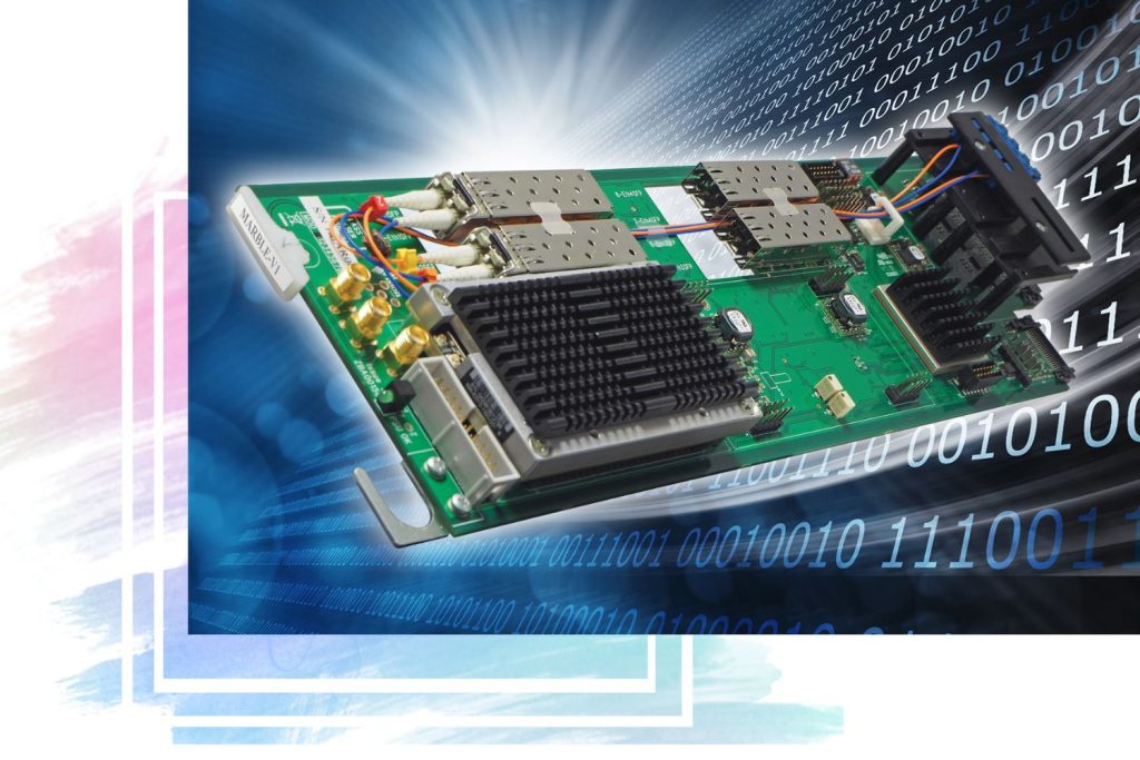
The future-proof M-SAFESWITCH-2 is a software app that runs on the MARBLE-V1 media processor – purpose-built GPU/CPU hardware that fits in the Vision frames.
Apps that are bought with the hardware can be replaced with different apps as needs change, helping you make the most of your budget.
More about MARBLE-V1
Featuring a powerful CPU/GPU processor, the MARBLE-V1 media processor hardware has six bi-directional SDI connections and four 10GbE SFP+ network interface ports (as well as eight bi-directional discrete AES stereo channels for future products).
The software app installed determines the functionality.
IP gateway and translation functionality included
The M-SAFESWITCH-2's gateway functionality can be used to integrate SDI into an IP environment or IP into an SDI environment.
Its IP to IP translation functionality can be used for network address translation, protocol conversion (between any of the input formats and any of the output formats), unicast to multicast address conversion and the creation of media firewalls.
Traffic shaping
With the potential for networks and IP receivers to not be very tolerant to bursty traffic, the M-SAFESWITCH-2 will ensure a nicely constructed IP output (with a choice of traffic shaping options), while its tolerant IP inputs are designed to be robust to bursty traffic.
Choice of timing sources
The M-M-SAFESWITCH-2 includes a framestore synchroniser timed to an external Black and Burst or tri-level syncs analogue reference or PTP.
The chosen reference is the global reference source for all input and output flows.
Reference redundancy offers peace of mind in case the main reference source is disrupted or needs to be taken down for maintenance, while cross-locking allows for mixed reference type and format installations if required.
There are up to ten options for the reference selection, selectable via VisionWeb. (See the Specification for full details.) Should the timing source at the top of the list become missing or invalid, the card will move down the list until it finds a valid timing reference source.
The output timing can be fully adjusted with respect to the chosen reference using three time-based controls (0 - 42ms adjustable in 0.1ms steps, 0 - 100us adjustable in 1us steps and 0 - 1us adjustable in 5ns steps), with the selected timing alignment global to all output flows.
Ten frames of flow input video delay (adjustable in one frames steps) allows delay compensation between the two inputs sources to each switch. An additional 60 frames of delay (adjustable in one frame steps) is available to further delay Source B on each switch - useful for input timing alignment when there are long Source A delays, such as those created by a graphics system. Ten frames of flow output video delay allows compensation for any big system delays.
Monitoring your signals
Features are provided to speed up system trouble shooting, particularly helpful with IP being more challenging to debug than SDI. Comprehensive SDI, IP and PTP monitoring information is available and can be used to generate SNMP traps.
The status indications available are video present and time present, video format, video black, video frozen, video error, Reference 1 and 2 present and time present, Reference 1 and 2 format, PTP master and backup clock present and time present, audio groups present, channels within the audio group present and channels within the audio group present but silent. The video black and video frozen alert can be delayed by up to 120 seconds to prevent false alarming during brief video pauses. The audio silence alert is triggered at an audio level of -93dbFS and can be delayed by up to 120 seconds to prevent false warnings during quiet audio periods.
PTP presence and statistics (network delay, delay variation, reference offset and sync period) are monitored.
The IP flow monitoring includes network error, packet loss, duplicated packets, packet delay variation, Ethernet interface ignored packets and Ethernet interface ignored multicast.
13 built-in test patterns can also help with fault finding.
Flexible control
All control is done remotely, with a choice of remote control and monitoring options for the M-SAFESWITCH-2 app running on the MARBLE-V1 media processor.
Hardware control options include an integrated control panel on the Vision 3 frame, the VisionPanel remote control panel and the SBB-4 smart button box.
Software control options include SNMP, our ASCII and JSON protocols and the VisionWeb web browser control. Try the M-SAFESWITCH-2 VisionWeb demo...
16 presets can be assigned and recalled.
- Find out more about the frame integrated control panel
- Find out more about VisionPanel
- Find out more about the SBB-4 smart button box
- Find out more about VisionWeb Control
- Find out more about SNMP
- Find out more about the ASCII and JSON protocols
Save rack space
Fitting in the standard Vision frames (currently available in 3U size), MARBLE-V1 is a space-saving 96mm x 325mm card that sits in one frame slot – allowing up to ten media processors in 3U. The double slot VR04, VR06 or VR07 frame rear module is used to access the four inputs and three outputs on the M-SAFESWITCH-2 app. Two of the outputs are configurable as IP or SDI, while the third output is fixed as IP.
Flexible assignment of the flows allows you to get the configuration you need. With the default being two outputs of Switch 1 and one output of Switch 2, it is possible to configure the product to give two or three outputs of either Switch instead, if required.
Protect your SDI output - with relay bypass protection
The VR07 frame rear module provides dual relay bypass protection when the M-SAFESWITCH-2 is used with both SDI inputs and SDI outputs to help maintain programme output.
The relay bypass protection protects the video output on frame power failure or if the MARBLE-V1 card loses power or is removed. It prevents signal loss by mechanically connecting an SDI input to an SDI output. SDI In 1 is connected to SDI 1 Out and SDI In 2 is connected to SDI 2 Out.
The VR07 additionally includes four 10GbE network interface, making it easy to upgrade to IP when required – with the resilience then provided by IP best practice.
Specs
M-SAFESWITCH-2 app running on MARBLE-V1 media processor...
MECHANICAL
‘Double slot’ Vision card 96mm x 303mm (96mm x 325mm including finger pull)
Weight: 355g
Power consumption: 25 Watts, plus 1 Watt for each SFP+ fitted to MARBLE-V1
INPUTS AND OUTPUTS
Inputs can be IP and/or SDI
Outputs can be IP and/or SDI
Six BNCs for SDI and up to four fibre SFP+ 10GbE IP network interfaces. Choice of fibre modules: either 850nm multi-mode (for up to 300m) or 1310nm single-mode (for up to 10km)
Inputs and outputs can be mixture of ST 2022 and ST 2110. Video can be passed between ST 2022 and ST 2110, although audio and any other non-video data will be lost
IP only, SDI to IP and IP to SDI applications require at least one SFP+ transceiver option, up to a maximum of four. Use one SFP+ to put all signals together, use two SFP+ to have main and protect or multicast and unicast on separate network interfaces and use three or four SFP+ to further separate flows
SDI only applications do not require any SFP+
Uses VR04, VR06 or VR07 frame rear modules. VR04 or VR07 must be used when more than two SFP+ are fitted
SDI VIDEO INPUTS
(NB. Some or all of the inputs can be IP instead)
Up to two 3Gb/s SDI inputs or four HD or SD SDI inputs. If the input is 3Gb/s then Input 1 and Input 3 should be used
270Mb/s or 1.5Gb/s or 3Gb/s serial compliant to SMPTE 259, SMPTE 292-1 and SMPTE 424/425-A
3Gb/s cable equalisation up to 100m using Belden 1694A. HD cable equalisation up to 140m with Belden 1694A or equivalent (approx. 100m with Belden 8281). SD cable equalisation >250m Belden 8281 or equivalent
IP FLOW INPUTS
(NB. Some or all of the inputs can be SDI instead)
Up to two 3Gb/s video over IP inputs or four HD or SD video over IP inputs. If the input is 3Gb/s then Flow input 1 and Flow input 3 should be used
Packet distribution is not important as variable input buffer will compensate for any timing irregularities. Any traffic shaping option from ST 2110-21 can be used, or packets can come from a device which does not meet the shaping requirement of ST 2110-21
A protect input for SMPTE ST 2022-7 seamless protection switching or the equivalent protect input in ST 2110-20 can come from any of the 10GbE IP network interfaces. This protects the stream from lost packets by creating two streams of the same data using different routing to the destination. Flow analyser handles the analysis and reconstruction of the protected stream. Any IP input can come from any of the 10GbE IP network interfaces and can either be multicast or unicast
SDI VIDEO OUTPUTS
(NB. Some or all of the outputs can be IP instead)
Up to two 3Gb/s or HD or SD SDI outputs (NB. Two 3Gb/s outputs available when both are routed to the switch with 3Gb/s inputs)
270Mb/s or 1.5Gb/s or 3Gb/s serial compliant to SMPTE 259, SMPTE 292-1 and SMPTE 424/425-A
IP FLOW OUTPUTS
(NB. Up to two of the outputs can be SDI instead)
Up to three 3Gb/s or HD or SD video over IP outputs (NB. Three 3Gb/s video over IP outputs available when all are routed to the switch with 3Gb/s inputs)
Any of the 10GbE IP network interfaces can be used to provide a protected output for SMPTE ST 2022-7 or ST 2110 seamless protection switching, which protects the stream from lost packets by creating two streams of the same data using different routing to the destination
Alternatively it is possible to have a unicast on some network interfaces and a multicast on others
RELAY BYPASS PROTECTION (SDI ONLY)
The VR07 frame rear module provides dual relay bypass protection when M-SAFESWITCH-2 is used with both SDI inputs and SDI outputs
The relay bypass protection protects the video output on frame power failure or if the MARBLE-V1 card loses power or is removed
An electromechanical relay switch on the VR07 needs power to hold the switch in one state and will revert to the other state (card bypass) on loss of power. It prevents signal loss by mechanically connecting an SDI input to an SDI output: SDI In 1 is connected to SDI 1 Out and SDI In 2 is connected to SDI 2 Out
NB. Use of the VR07 requires issue 5 or later of MARBLE-V1
VIDEO FORMATS SUPPORTED
The video formats supported are 625i, 525i, 720p50, 720p59.94, 720p60, 1080i50, 1080i59.94, 1080i60, 1080p23.98, 1080p24, 1080p25, 1080p29.97, 1080p30, 1080p50, 1080p59.94, 1080p60, 1080PsF23.98, 1080PsF24, 1080PsF25, 1080PsF29.97, 1080PsF30, 2048x1080p23.98*, 2048x1080p24*, 2048x1080p25*, 2048x1080p29.97*, 2048x1080p30*, 2048x1080PsF23.98*, 2048x1080PsF24*, 2048x1080PsF25*, 2048x1080PsF29.97*, 2048x1080PsF30* (*= YUV 4:2:2 10 bit)
IP PROTOCOLS
Protocols supported on network interfaces: SMPTE ST 2022-6, SMPTE ST 2022-7, SMPTE ST 2110-20 (uncompressed video), SMPTE ST 2110-10 (system architecture and synchronisation), SMPTE ST 2110-21 (traffic shaping), IGMPv3, ARP, ICMP ping, IPv4, IEEE802.1q, VLAN, IEEE802.3-2012 (10G Ethernet), LLDP
Packing options of the ST 2110 output are selectable per flow between BPM and GPM (Block Packing Mode or General Packing Mode)
Packet shaping and distribution (compulsory in ST 2110 and optional in ST 2022) is selectable per flow between TPNL and TPN (narrow linear or narrow gapped packet distribution). There is also a mode for burst packet distribution with a control for the burst rate limit. This is for connecting between Crystal Vision and other compatible devices that allow for a reduced transmission delay
SMPTE ST 2022-7 and ST 2110 flow protection facilitates the dual stream output
MANUAL AND AUTOMATIC SWITCHING
M-SAFESWITCH-2 provides two 2 x 1 clean switches
These can be switched either manually (using the Switch to A and Switch to B buttons) or automatically
In auto mode M-SAFESWITCH-2 will always want to be on its primary input (Source A), only switching to secondary input B if there are user-defined faults on the primary input. It is possible to select from ten different parameters to automatically trigger the switch (see AUTO SWITCH PARAMETERS)
After switching away from a faulty input, M-SAFESWITCH-2 can be set to switch back automatically or by user intervention
When the Restore to A mode is set to "Delayed", M-SAFESWITCH-2 will automatically return to Source A once it has been clear of the monitored faults for the time set on the Restore delay slider, with the time programmable between two and 60 seconds
When the Restore to A mode is set to "Latched", M-SAFESWITCH-2 will stay switched to Source B until the user manually restores it to Source A
The framestore synchroniser in each input stream will ensure that both inputs to the switch are correctly timed to the reference so that there is no disruption during a switch
M-SAFESWITCH-2 can cope with signal path delays of ten frames between the input flows. Additional delay of up to 60 frames can be applied to Source B of each switch, should the Source A delay be greater than the ten frames adjustment provided at the flow input stage
AUTO SWITCH PARAMETERS
M-SAFESWITCH-2 performs checks on the following ten parameters which can trigger an automatic switch, with the user able to select a number of parameters in any combination. Different parameters can be chosen for each switch. Switch tolerance can be applied which allows the error to exist for up to ten frames before the auto switch will occur
- Input not present
- Incorrect input format
- Video black
- Video frozen
- Video error
- Network error
- Audio all selected missing
- Audio any selected missing
- Audio all selected silent
- Audio any selected silent
In addition to the ten frames switch tolerance, detection delay can be applied to the video black and video frozen auto switch parameters which allows the picture to remain black or frozen between 1 and 120 seconds before the auto switch will occur. Black and frozen delays can be individually set, but each is common to both switches
Black is detected when all pixels are black – a single non-black pixel resets the detection delay period
Frozen is detected by splitting each video frame into a grid of image tiles where the sum of pixel values within each tile is computed and compared against the previous frame. If the difference between sums is greater than the in-built frozen detection threshold, the image is detected as not frozen and this resets the detection delay period. This allows frozen video to be detected even in the presence of noise or ‘bad’ pixels
The four audio parameters are applicable to SDI and ST 2022. Individual audio channels can be selected and a switch can be triggered if any or all of the audio channels are missing or are silent. In addition to the ten frames switch tolerance, detection delay can be applied to the audio silence switch parameters which allows the audio to remain silent between 1 and 120 seconds before the auto switch will occur
ROUTING
The two clean switches can each select between the four input flows for their Source A and Source B
The default setting – which gives a dual channel 2 x 1 safe switch – is Switch 1 to Flow output 1 and Flow output 3 and Switch 2 to Flow output 2. The default inputs to Switch 1 are Flow input 1 and Flow input 3. The default inputs to Switch 2 are Flow input 2 and Flow input 4
It is also possible to configure the product to give two or three outputs of Switch 1 or Switch 2 instead, if required (NB. Third output only available in IP)
VIDEO LOSS CONTROLS
The video loss controls allow the user to select what will happen to an output flow in the event that the input is lost. The user can specify to freeze the last good frame or show a black or blue screen or 100% colour bars (with or without an initial delay of three seconds). No output can also be selected. This is independently adjustable on each flow
TEST PATTERNS
The test pattern controls allow the user to override an input and force the output flow to output a test pattern including Colour Bars, Blue, Black, EqCheck, PllCheck, Pluge, Checkfield, Grey Horizontal Steps, Grey Vertical Steps, Luma Horizontal Ramp, Luma Vertical Ramp, Cycle Colour or Checker Board, or to freeze the picture. This is independently adjustable on each flow
AUDIO MUTE CONTROL
The output audio mute control allows the user to mute the audio embedded within any of the SDI or ST 2022 outputs
SYNCHRONISER AND TIMING ADJUSTMENTS
Video sources are synchronised to common reference timing source
Choice of timing options:
- PTP (SMPTE ST 2059-2) master and backup, via 10GbE IP network interface
- Two tri-level syncs or analogue Black and Burst references (Reference 1 and Reference 2), connected via the Vision 3 frame
- SDI video input, where available (defaults to SDI 1)
Chosen reference is the global reference source for all inputs and outputs
There are up to ten options for the reference selection, selectable via VisionWeb. The hierarchy runs from left to right – should the timing source at the top of the list become missing or invalid, the app will move down the list until it finds a valid timing reference source. When used with IP inputs, the SDI reference option is not applicable and therefore the reference will move to the next valid timing source:- PTP>Ref1>Ref2>Hold
- PTP>Ref1>Hold
- PTP>Ref2>Ref1>Hold
- PTP>Ref2>Hold
- PTP>Hold
- PTP>Ref1>Ref2>SDI>Hold
- PTP>Ref1>SDI>Hold
- PTP>Ref2>Ref1>SDI>Hold
- PTP>Ref2>SDI>Hold
- PTP>SDI>Hold
(“PTP” means PTP Master>PTP Backup. “SDI” means SDI1>SDI2>SDI3>SDI4>SDI5>SDI6, depending on number of SDI available. "Hold" means it will hold the timing of the last good reference)
When using video reference, video inputs can be different formats but only inputs with the same frame rate as reference video will be locked to that reference. Input signals of same frame rate as reference will be locked together and locked to external reference. Inputs with a differing frame rate will be locked and maintain timing with no drift, but their sync point will be undefined (all same frame rate signals will, however, be locked to each other)
When using PTP reference, input sources of different format and/or frame rate will all be correctly locked to the PTP reference
PTP timing reference should be used when there is a ST 2110-20 output to ensure the RTP timestamp is related to the time of day. However without a PTP reference, a valid ST 2110-20 signal will still be generated using a free running RTP timestamp
When Auto relock enable is selected, the card will automatically relock when a lost reference is restored. Selecting Force lock (with Auto relock disabled) will force the synchroniser to relock after a reference is restored, and can be activated at a non-critical time to avoid video disturbance
Output timing can be fully adjusted with respect to the reference using three time-based controls: 0 - 42ms adjustable in 0.1ms steps, 0 - 100us adjustable in 1us steps and 0 - 1us adjustable in 5ns steps. Sub frame timing alignment to chosen reference is global to all outputs
Ten frames of flow input video delay (adjustable in one frames steps) allows delay compensation between the two inputs sources to each switch
Additional 60 frames of delay (adjustable in one frame steps) is available to further delay Source B on each switch. This is useful for input timing alignment when there are long Source A delays, such as those created by a graphics system
Ten frames of flow output video delay (adjustable in one frame steps) allows compensation for any big system delays
ANCILLARY DATA
All ancillary data (including audio and locked Dolby E) is passed from SDI or ST 2022 input to SDI or ST 2022 output. When ST 2110 input or output is selected, all ancillary data is discarded
LED INDICATION OF:
Power okay
PRESETS
The current app settings can be saved in one of 16 locations to be recalled as required
SIGNAL MONITORING
Comprehensive SDI, IP and PTP monitoring information is available and can be used to generate SNMP traps
Checks are performed on the inputs and outputs for the following video and audio parameters:
- Video present and time present
- Video format
- Video black
- Video frozen
- Video error (inputs only)
- Audio group 1 present
- Audio group 2 present
- Audio group 3 present
- Audio group 4 present
- Audio present on group 1 channel 1
- Audio present on group 1 channel 2
- Audio present on group 1 channel 3
- Audio present on group 1 channel 4
- Audio present on group 2 channel 5
- Audio present on group 2 channel 6
- Audio present on group 2 channel 7
- Audio present on group 2 channel 8
- Audio present on group 3 channel 9
- Audio present on group 3 channel 10
- Audio present on group 3 channel 11
- Audio present on group 3 channel 12
- Audio present on group 4 channel 13
- Audio present on group 4 channel 14
- Audio present on group 4 channel 15
- Audio present on group 4 channel 16
- Silence group 1 channel 1
- Silence group 1 channel 2
- Silence group 1 channel 3
- Silence group 1 channel 4
- Silence group 2 channel 5
- Silence group 2 channel 6
- Silence group 2 channel 7
- Silence group 2 channel 8
- Silence group 3 channel 9
- Silence group 3 channel 10
- Silence group 3 channel 11
- Silence group 3 channel 12
- Silence group 4 channel 13
- Silence group 4 channel 14
- Silence group 4 channel 15
- Silence group 4 channel 16
Black or frozen video will be indicated by an amber LED. This alert can be delayed by 1-120 seconds to prevent false warnings during brief video pauses
The audio silence alert is triggered at an audio level of -93dbFS and can be delayed by 1-120 seconds to prevent false warnings during quiet audio periods
The following IP parameters are monitored for input flows:
- Network error
- Packet loss
- Duplicated packets
- Packet delay variation. Shown as the skew (difference in time of packet arrival) between the main and protected input, and also as the min and max nano second gap between the packets on each input
The Ethernet interfaces are monitored for:
- Count of packets ignored by the app (general network traffic non-media packets, which do not require processing by the app). Jumps in 100 step increments indicate network traffic flood
- Ignored multicast packets. LED indicates multicast traffic not requested by the app is present on the Ethernet Interface, indicating incorrectly configured IGMP at the network switch
References are monitored for:
- Reference 1 and 2 present and time present
- Reference 1 and 2 format
- PTP master and backup clock present and time present
- PTP statistics – network delay, delay variation, reference offset and sync period
REMOTE CONTROL
Software:
VisionWeb Control is available via the web server on the frame and allows control and monitoring using a standard web browser on a computer, tablet or phone
SNMP monitoring and control available as standard
Control using ASCII and JSON protocols
Hardware:
Control from integrated control panel on Vision 3 frame
Control from VisionPanel 3U remote panel
SBB-4 smart button box connects to the frame via Ethernet and provides four programmable LCD switches (which are configured for each order). The SBB-4 uses information from VisionWeb for settings. Uses Power over Ethernet so must be used with PoE enabled switch
What outputs do I get?
Signal inputs and outputs are accessed by using an appropriate rear module.
The Vision rear modules slot on at the back of the frame and typically feature BNC, Micro BNC, D-Type and LC fibre connectors.
There are three rear modules available for the M-SAFESWITCH-2...
VR04 rear module label and connections
More about the VR04
Connectors: 6 BNCs and 4 dual LC fibre
Frame slots used: 2
Boards in 3U: 10
Why use it: It's ideal for any M-SAFESWITCH-2 application, and can be used with up to four SFP+
Also used for: M-CLEANIT, M-COCO-2, M-KEY, M-PIP, M-SAFESWITCH-2L, M-SAFIRE, M-VIVID100-3, M-VIVID200-2, M-VIVID400-2, M-VIVID800 and M-WEBKEY
VR06 rear module label and connections
More about the VR06
Connectors: 6 BNCs, 1 D-Type and 2 dual LC fibre
Frame slots used: 2
Boards in 3U: 10
Why use it: You can use it for any M-SAFESWITCH-2 application involving two or less SFP+
Also used for: M-CLEANIT, M-COCO-2, M-GWIPSDI-6, M-GWSDIIP-6, M-KEY, M-PIP, M-SAFESWITCH-2L, M-SAFIRE, M-VIVID100-3, M-VIVID200-2, M-VIVID400-2, M-VIVID800 and M-WEBKEY
VR07 rear module label and connections
More about the VR07
Connectors:6 BNCs and 4 dual LC fibre (with dual SDI relay bypass)
Frame slots used: 2
Boards in 3U: 10
Why use it: You want SDI relay bypass protection
Also used for: M-CLEANIT, M-COCO-2, M-KEY, M-PIP, M-SAFESWITCH-2L, M-SAFIRE, M-VIVID200-2, M-VIVID400-2, M-VIVID800 and M-WEBKEY
For more visual technical information, download the M-SAFESWITCH-2 block diagram.
What do I order?
First you need the software app...
- M-SAFESWITCH-2
- IP/SDI dual channel 2 x 1 fail-safe switch. Supports 3G/HD/SD and ST 2022-6, ST 2022-7 and ST 2110-20 protocols. Software app which runs on the MARBLE-V1 media processor
Now choose your media processor hardware and SFP+ modules...
Next select your frame...
- Vision 3
- 3U frame with integrated control panel and smart CPU for up to 20 Crystal Vision cards from the Vision range. Includes two PSU3-VF power supplies for redundancy. Allows Ethernet connection to a PC
You need a rear module to access your inputs and outputs...
- VR04
-
Two slot frame rear module. Allows ten M-SAFESWITCH-2 in 3U. Inputs and outputs can be mixture of SDI via BNCs and IP via up to four 10GbE network interfaces on dual LC. Gives access to four HD/SD (two 3Gb/s) SDI or IP inputs, two SDI or IP outputs and one fixed IP output
- VR06
- Two slot frame rear module. Allows ten M-SAFESWITCH-2 in 3U. Inputs and outputs can be mixture of SDI via BNCs and IP via up to two 10GbE network interfaces on dual LC. Gives access to four HD/SD (two 3Gb/s) SDI or IP inputs, two SDI or IP outputs and one fixed IP output
- VR07
-
Two slot frame rear module. Allows ten M-SAFESWITCH-2 in 3U. Inputs and outputs can be mixture of SDI via BNCs and IP via up to four 10GbE network interfaces on dual LC. Provides dual relay bypass protection for up to two inputs when used with SDI inputs and outputs. Gives access to four HD/SD (two 3Gb/s) SDI or IP inputs, two SDI or IP outputs and one fixed IP output. NB. Use of the VR07 requires issue 5 or later of MARBLE-V1
Next - control. Complimentary options include the frame's integrated control panel, the VisionWeb web browser control, SNMP and our ASCII and JSON protocols. Alternatively order one of the items below...
- VisionPanel
- 3U Ethernet remote control panel with touch screen
- SBB-4
- Smart button box with four programmable LCD switches. It is powered by PoE (Power over Ethernet) and therefore needs to be connected to a PoE enabled switch
Finally - extended support if required...
- App support
- Purchase with M-SAFESWITCH-2 app to get software upgrades for changes in standards, new features and bug fixes plus telephone and e-mail operational support (with support for the first year included for free)
Who's using it?
Users of the routing switches in the Vision and Indigo ranges include...
|
![]()
|
Do more...
- What does it cost? Request a quote for the M-SAFESWITCH-2...
- Want to hire instead? Request a hire quote...
- What controls has it got? Try out the VisionWeb demo for the M-SAFESWITCH-2...
- Want more information? Get the M-SAFESWITCH-2 user manual (and SNMP MIB) by signing up for the Registered Area now
- Should you buy app support? Find out more about it in the App support conditions document
- The M-SAFESWITCH-2 app runs on the MARBLE-V1 media processor hardware which needs to be housed in a Vision 3 rack frame - find out more about the frame...
Explore more...

From the Vision frame system...
- MARBLE-V1 media processor hardware which runs Crystal Vision's software apps
- M-SAFESWITCH-2L IP/SDI dual channel 2 X 1 clean switch and legaliser app
From the Indigo frame system...
- Safe Switch 3G 3G/HD/SD 2 x 2 clean switch
- Safe Switch-L 3G 3G/HD/SD 2 x 2 clean switch (extra outputs)
- SW803 3G 3G/HD/SD 8 x 3 crosspoint routing switch
Not sure which switch is best for your application? Have a look at our Indigo and Vision routing switches comparison chart to help you make a decision...
Crystal Vision Ltd. is registered in England number 03139895. Registered office: Lion Technology Park, Station Road East, Whittlesford, Cambridge, CB22 4WL, England.
Tel: +44 (0)1223 497049 E-mail: sales@crystalvision.tv