Contact us...
Download...
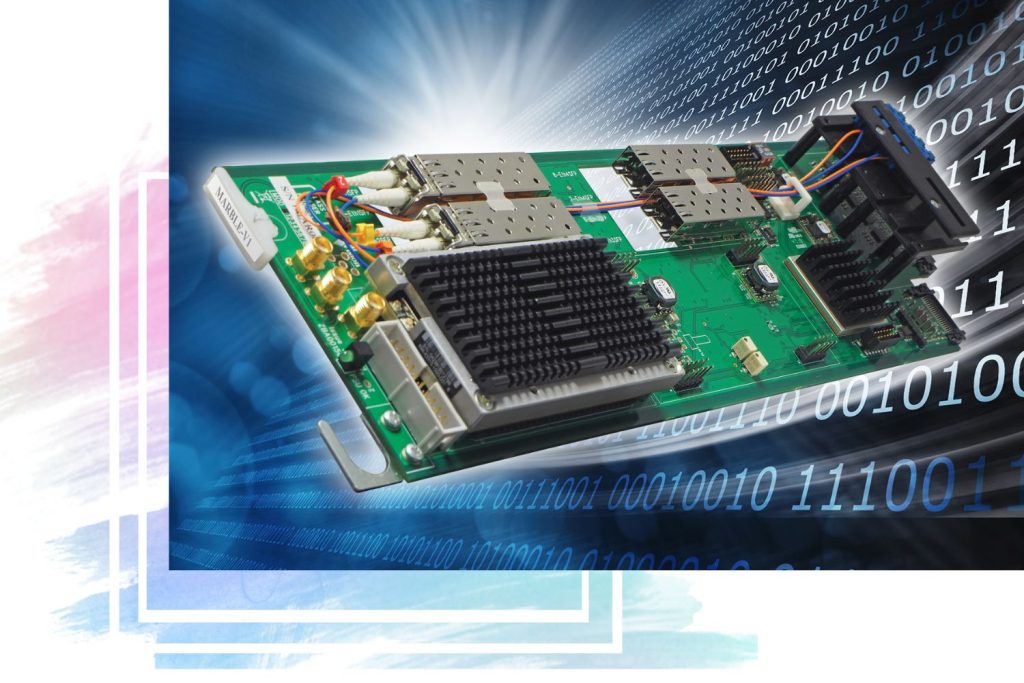
Safe Switch 3G clean routing switch


What is it?
3G/HD/SD intelligent and clean 2 x 2 fail-safe routing switch.
Reason to choose it...
Because it's the only way to really guarantee a clean switch – always protecting the output and keeping the MPEG encoder happy. With a full framestore synchroniser on each input (plus the ability to delay the earliest arriving input by up to 25 frames), it can correct for any timing difference between the two inputs – resulting in no disruption to the output picture when a switch takes place, even if you lose your reference. It will choose the best input to use (select from 18 different video and audio fault conditions) and it includes relay bypass protection.
Ideal for...
You need a 2 x 2 switch you can rely on to give you a disruption-free output at all times – whether for your planned maintenance switches, or as a very sophisticated auto changeover switch where you want to specify the fault conditions that will auto-trigger the switch. See who's using it.
Control it...
Try out the Safe Switch 3G VisionWeb GUI (opens in new window) – you'll see how easy it is to operate Safe Switch 3G from your web browser, while exploring the full functionality of the product.
Got a question?
We would be very happy to answer any questions you've got about the Safe Switch 3G. Either send us an e-mail or get an immediate response by speaking to us now on our Live Chat...
- Main features
- Details
- Specs
- What outputs do I get?
- What do I order?
- Who's using it?
Main features
- Clean and intelligent 2 x 2 switch
- Works with 3Gb/s, HD and SD (both inputs must be same standard)
- Switch it manually: ideal for planned maintenance switches to manually re-route good signal around broken equipment
- Use it as an auto changeover switch and switch it automatically: can be used as intelligent emergency transmission switch
- Get no disruption to the output picture when a switch takes place: a full framestore synchroniser on each input means it can correct for any timing difference between the two inputs
- Delay the earliest arriving input by up to 25 frames in one frame steps - ideal if the backup signal has gone through less processing equipment and arrives several frames earlier than the main input
- No problem if you lose your reference: will changes its timing smoothly between the reference and the inputs, keeping the output valid at all times
- Select from 18 fault conditions to automatically trigger a switch, and monitor any number of parameters in any combination - will work to most significant fault when deciding which input to select
- Discover faults that need fixing: set up two fault indications with their own list of chosen parameters and get very flexible monitoring
- Inputs and outputs accessed by using an appropriate rear module (either RM54 or RM66)
- Optional integrated fibre output connectivity (with RM66 frame rear module) means you won’t be limited by cable lengths
- Prevent signal loss: relay bypass protection on power failure or board removal for extra peace of mind (with RM54 rear module)
- Housed in Indigo rack frames
- Space-saving: 100mm x 266mm module allows 12 Safe Switch 3G in 2U (six in 1U and two in desk top box)
- Flexible control: GPI, frame integrated control panel, VisionPanel remote control panel, SBB-4 smart button box, SNMP, ASCII and JSON protocols, Statesman Lite PC software or the web browser-based VisionWeb Control
- Exceptional GPIs functionality - six bi-directional GPIs can be configured as either GPI inputs or GPI outputs
- Five year warranty (with product registration)
- This product is available to either purchase or hire, with hire pricing typically 6% of list price per week (with one week minimum hire period and £200 minimum charge)
Details
The way to guarantee a clean switch
Safe Switch 3G is the way to guarantee a clean switch – and protect your output.
It provides clean and intelligent 2 x 2 switching between two 3Gb/s, HD or SD sources containing up to four groups of embedded audio, with the full framestore synchroniser on each input allowing it to correct for any timing difference (big or small) between the two inputs – resulting in no disruption to the output picture when a switch takes place.
Ideal for planned maintenance switches to manually re-route a good signal around broken equipment, it can also be used as an intelligent auto changeover switch for those emergency transmission situations by engineers who do not want to restrict themselves to timed inputs, with the option of selecting from 18 different fault conditions to automatically trigger the switch.
With the ability to deal with any type of timing issues, Safe Switch 3G gives you a clean switch that can survive even the most catastrophic failure. It can even lose the reference signal and not affect the output. Your viewers will never know there’s a problem.
Why do you need a clean switch?
Continuity of service is vital and it’s crucial you don’t go off air. This is why Safe Switch 3G is ideal for use on the final output stage of a transmission system, before the signal gets to the MPEG encoder.
Typically the main programme path goes through various ‘boxes’ before going into a 2 x 1 switch. The second input of the switch is fed the backup signal – often the same material but gone a more simplified route. If something goes wrong on the main programme path you can switch to backup, but the issue is that there will be a delay because the backup has gone through less ‘boxes’.
This time difference between the main and backup signals upsets the MPEG encoder. With the MPEG encoder only transmitting differences between one frame and the next, the consequence of a sudden jump in timing is that the excessive information generated by the disrupted stream causes the MPEG encoder to reach its bandwidth limit and fall over. One frame glitch on the input to the MPEG encoder could lead to up to 15 frames of corrupted video coming out of it.
To balance the delays between the main and backup feeds you could of course use three boards – a switch and two synchronisers – but Crystal Vision saves you space and money by doing it all on one board: Safe Switch 3G.
Not only can Safe Switch 3G correct input timing differences up to one frame, it can also delay the earliest arriving input by up to 25 frames in one frame steps - making it perfect for those occasions when the backup signal has gone through less processing equipment and so arrives several frames earlier than the main input.
Safe Switch 3G is a 2 x 2 switch and you could use the second output to feed a backup redundant MPEG encoder, or your second output could go a completely different route to the transmitter after the MPEG encoder – such as via a microwave link, with the other feed going via fibre.
Another application could be to switch between the main and backup of a server system. Here the second output could be fed to a preview monitor for monitoring the servers.
Sometimes you need to switch to backup in non-emergency situations – when one of the ‘boxes’ in the chain needs fixing or updating and you want to ignore the path that the box is in.
For all these applications Safe Switch 3G will provide the most robust solution possible.
Switch it manually or automatically
Safe Switch 3G can either be switched manually or automatically – making it equally suited to planned maintenance switches or emergency transmission applications.
Manual switching takes place according to the setting of the switch timing control. Automatic switching will occur at the switching point given in SMPTE RP168:2009 when the switch timing is set to ‘Field’ or ‘Frame’, or immediately if triggered by the input missing or input video standard fault conditions.
There’s no underlying preference for either input. Being a symmetrical switch means you can select your preferred input by means of a 2 x 2 routing grid, rather than having pre-assigned main and secondary feeds.
Each of the two inputs can be switched to either or both of the two outputs, with up to two reclocked feeds of each switched signal available. The two inputs must be the same standard.
There are lots of switching options available. For example, Output 2 can be configured to be the opposite of Output 1, making 1 a preview that will always show what will be transmitted if you change the switch allowing you to easily swap to a good secondary feed. Output 2 can be requested to be the same as Output 1 – like a 2 x 1 switch with more outputs.
How to get a really clean switch
With Safe Switch 3G you never have to worry about a difference in timing between your main and backup feeds – you are always going to get a clean and seamless switch.
The synchroniser in each input stream will ensure that both inputs to the switch are correctly timed to the external analogue reference so that there is no disruption during a switch. The synchronisers act as a self-adjusting delay of between 0 and 1 frame, allowing a clean transition between the two channels even if their relative timing has slipped.
Safe Switch 3G can also cope with signal path delays of +/-25 frames between the two inputs and can delay the earliest arriving input by up to 25 frames in one frame steps.
It is easy to compensate for mistimed sources elsewhere in the system by adjusting the output timing relative to the reference through an entire frame using horizontal and vertical settings.
Cross-locking allows a 3Gb/s, HD or SD input to be referenced to either HD tri-level syncs or SD Black and Burst – allowing the convenient use of any existing timing signals.
Loss of reference protection
Loss of reference protection – where Safe Switch 3G will change its timing smoothly between the reference and the inputs, keeping the output valid at all times – is an unusual and technically-advanced feature which further extends the board’s primary purpose of protecting the output from any disruption.
In normal operation the output timing is derived from the reference. If the reference is lost, Safe Switch 3G will switch to input 1 or (if not available or subsequently lost) input 2 as an alternative clock source, changing to the same sample/line/frame rate as the input without disrupting the output video.
If the signal input is genlocked to the reference the output will be unchanged, while if not locked to the reference the output data rate will change smoothly, slowly drifting relative to the reference and remaining in spec at all times.
If the reference returns, the board will gently drift from the input source to line up with the reference over a period of time – again without disrupting the output signal.
Intelligent automatic switching - select from 18 fault conditions
Safe Switch 3G constantly checks both of the inputs so that the output of the switch always remains proper and valid.
It can be set to automatically switch away from the user-selected input if it does not meet the set requirements. It extracts information about various parts of the video signal to decide which of the two inputs is better, based on the engineer’s selection of which faults are significant.
The 18 video and audio parameters which can be selected to perform a switch, and which are listed in order of priority, are input missing, input video standard incorrect, EDH missing, EDH full field error, EDH active picture error, line CRC error, audio group 1 missing, audio group 2 missing, audio group 3 missing, audio group 4 missing, active video black, Ancillary Timecode missing, Ancillary Timecode frozen, active video frozen and audio silence on any channel in a selected group. Safe Switch 3G will additionally report the reference video standard.
The Black Threshold control can be used to determine the level of digital black required before a switch is made. With some processes – such as video compression or converting to analogue and back – introducing small changes frame-to-frame even if the input picture is frozen, the processed frozen picture detection feature allows Safe Switch 3G to intelligently distinguish between this noise and real changes in the picture content – and so correctly flag up an active video frozen error condition. Audio silence level settings can be selected from -48dBFs, -54dBFs, -60dBFs, -66dBFs, -72dBFs, -78dBFs, -84dBFs and -90dBFs.
There is the option to set a time period of between two and 120 seconds before the video black, Ancillary Timecode frozen, video frozen and audio silence parameters trigger a switch – adding further flexibility.
Safe Switch 3G will switch away from an error on the user-selected input only if the other input is free of that fault. If both inputs have different alarms, it will use the most significant alarm to decide which feed to select. It works down the list, checking everything that has been chosen by the engineer as being of interest. As long as it does not find an error on the selected input without a corresponding error on the non-selected input, it stays with the selected input. If it finds such an error it switches to the other input.
The user can decide what constitutes a fault separately for each input - specifying what he cares about on each signal with the logic then selecting the best input. This feature provides a solution in situations where the backup signal may not contain everything required in the main signal, allowing selection between signals with different characteristics – such as a live main feed and an inherently frozen apology caption on the backup.
Following a switch it can either reselect the main feed automatically (with the option to set a time period for which the signal must be good before switching back) or by user intervention.
Easy to monitor for any faults
In addition to the automatic switching, two fault indications (Fault Indicator A and Fault Indicator B) can also be set and assigned to VisionWeb LEDs, Statesman Lite LEDs, GPIs or SNMP traps, allowing very flexible monitoring.
These fault indications are very useful, whatever type of switching you are doing. If Safe Switch 3G is set to manual switching, the fault indications will tell you that you should switch. If Safe Switch 3G is set to auto switching, the fault indications will inform you of the faults that need fixing – otherwise the board could just switch without you knowing why.
The fault indications each have their own list of chosen parameters which can be different from the auto switch selection. Each fault indication can be assigned to a specific input, to either input, or to only become active if both inputs show a selected fault. For example, you could monitor for audio silence on your main channel and get a separate indication if both channels freeze.
Fibre output connectivity - on the board
It’s easy to give Safe Switch 3G integrated fibre output connectivity by ordering the FOP fibre output option – and still only use a single frame slot.
Designed for SMPTE 297-2006 short-haul applications the FOP uses a Class I laser and transmits an optical output.
With a FOP fitted, Safe Switch 3G will provide an optical feed of output 1 and an electrical feed of output 2. Perfect if you’re using the switch as the last point on the output of a studio and need to send the signal over a long distance to the central router or station transmission output.
Having the fibre output integral to the board reduces the need to use up additional rack space for separate fibre optic transmitters – as well as saving you money.
Safe Switch 3G can also support a CWDM laser if required.
Choose your control - with the most flexible GPIs
Control options include an integrated control panel on the AE frame, the VisionPanel remote control panel, the SBB-4 smart button box, SNMP, our ASCII and JSON protocols, the Statesman Lite PC software and the VisionWeb web browser control. Try the Safe Switch 3G VisionWeb demo...
Safe Switch 3G has exceptional GPIs flexibility – ideal for GPI-focused broadcasters who want to have direct control of the board. The six GPIs are all bi-directional, allowing them to be configured as either GPI inputs or GPI outputs and so giving you real flexibility when setting up buttons and lights for GPI control and monitoring of alarm conditions.
- Find out more about the frame integrated control panel
- Find out more about VisionPanel
- Find out more about the SBB-4 smart button box
- Find out more about VisionWeb Control
- Find out more about Statesman Lite
- Find out more about SNMP
- Find out more about the ASCII and JSON protocols
- Find out more about GPIs
Frames, rear modules - and relay bypass protection
Safe Switch 3G is a space-saving 'single slot' 100mm x 266mm module which can be housed alongside any other products in the standard Crystal Vision frames – available in 2U, 1U and desk top box sizes. Up to 12 Safe Switch 3G modules can fit in a 2U frame.
To access the inputs and outputs, Safe Switch 3G is used with either the RM54 frame rear module for standard applications or the RM66 for fibre output applications.
The RM54 provides the two inputs, two feeds of output 1, one feed of output 2 and an analogue reference connection.
The RM66 provides the two inputs, one optical feed of output 1, one electrical feed of output 2 and an analogue reference connection.
The RM54 rear module includes relay bypass protection on power failure or board removal, giving the system an extra layer of security and preventing signal loss.
Specs
MECHANICAL
Standard Crystal Vision module 266mm x 100mm
Weight: 180g
Power consumption: 11.9 Watts (plus 0.6 Watts for FOP)
VIDEO INPUTS
Two 3Gb/s, HD or SD inputs. The two inputs must be the same standard
270Mb/s or 1.5Gb/s or 3Gb/s serial compliant to SMPTE 259M, SMPTE 292M and SMPTE 424M
The video formats supported are 625, 525, 720p50, 720p59.94, 1080i50, 1080i59.94, 1080p50 and 1080p59.94
3Gb/s cable equalisation up to 80m using Belden 1694A. HD cable equalisation up to 140m with Belden 1694A or equivalent (approx. 100m with Belden 8281). SD cable equalisation >250m Belden 8281 or equivalent
Input return loss: - 15dB for 50MHz to 1.5GHz
Auto 50/59.94Hz and video format selection. When enabled the video standard will automatically follow the standard on input 1
Symmetrical switch which allows the user to select the ‘preferred’ input by means of a 2 x 2 routing grid. The input selected manually will be connected to the output unless it has a higher priority user-indicated error than the unselected input
VIDEO OUTPUTS
Two independent ports with two feeds of output 1 and one feed of output 2 using RM54 frame rear module, or one optical feed of output 1 and one electrical feed of output 2 using RM66
270Mb/s or 1.5Gb/s or 3Gb/s serial compliant to SMPTE 259M, SMPTE 292M and SMPTE 424M. Output follows the input format
Output 2 can be requested to be the same as output 1
Output 2 can be requested to be the opposite of Output 1, making 2 a preview
INTEGRATED FIBRE OUTPUT OPTION
Safe Switch 3G can be given integrated fibre output connectivity by fitting the FOP fibre output option. The FOP should be fitted at the factory
To access the optical output an RM66 frame rear module must be used
When fitted with a FOP, Safe Switch 3G can be housed in any frame slot position but due to its extra height it is not possible to place Standard Definition or audio boards directly above it when the Safe Switch 3G is in even numbered slot positions. 3Gb/s and HD boards do not share this restriction
FOP meets the SMPTE 297-2006 short-haul specification, allowing operation with single-mode and multi-mode fibre
Connector type: SC/PC
Optical power: Max -0.0dBm, min -5.0dBm (typical -2.0dBm or 630uW)
Fibre pigtail: Single-mode 8/125uM
Optical wavelength: 1290-1330nm (1310 typical)
Extinction ratio: 7.5dB
Laser safety classification: Class 1 (EN 60825), Class I (21CFR1040.10)
RELAY BYPASS PROTECTION
The RM54 frame rear module provides relay bypass protection. An electromechanical relay switch needs power to hold the switch in one state and will revert to the other state (board bypass) on loss of power. It prevents signal loss by mechanically connecting the switch’s main input to its output 1 on complete frame power failure or board removal
ANALOGUE REFERENCE
Tri-level syncs or analogue Black and Burst or video
3Gb/s, HD or SD source can use either type of reference
When cross-locking it is necessary for both the video input and reference to share the same frame rate
Amplitude of syncs 150mV to 600mV
Link on PCB selects 75 ohm termination or high impedance
TIMING ADJUSTMENTS
The framestore synchroniser in each input stream will ensure that both inputs to the switch are correctly timed to the external analogue reference so that there is no disruption during a switch
The synchronisers are intended to allow for inputs that are frequency-locked to the reference even if they are not co-timed
The synchronisation will occur solely at the start of frame point (the SAV of the switching line)
The synchronisers act as a self-adjusting delay of between 0 and 1 frame allowing a clean transition between the two channels even if their relative timing has slipped
The timing can be fully adjusted using horizontal and vertical settings. Increasing the vertical setting will delay the output relative to the reference in increments of one line. Increasing the horizontal setting will increase this delay in increments of approx. 74ns for SD, 13.5ns for HD and 6.7ns for 3G. The output timing can be adjusted through an entire frame relative to the reference
Safe Switch 3G can cope with signal path delays of +/-25 frames between the two inputs. Input timing differences greater than one frame can be corrected by delaying the earliest arriving input by up to 25 frames in one frame steps
LOSS OF REFERENCE PROTECTION
With loss of reference protection, Safe Switch 3G will change its timing smoothly between the reference and the inputs, keeping the output valid at all times
In normal operation the output timing is derived from the reference
If the reference is lost, Safe Switch 3G will switch to input 1 or (if not available or subsequently lost) input 2 as an alternative clock source, changing to the same sample/line/frame rate as the input without disrupting the output video. If the signal input is genlocked to the reference, the output will be unchanged. If not locked to the reference, the output data rate will change smoothly, slowly drifting relative to the reference and remaining in spec at all times. To avoid disruption the output timing is not changed to match the signal input
If the reference returns, the board will gently drift from the input source to line up with the reference over a period of time without disrupting the output signal
If neither input 1 nor 2 can be relied upon, the ‘crash lock to reference when reapplied’ control allows Safe Switch 3G to hard lock to the reference when it is present. If neither input 1 nor 2 is available as an alternative reference source, the Safe Switch 3G will freerun on loss of reference. If the reference is then reapplied, Safe Switch 3G will stay in freerun mode until a hard lock to reference occurs
DELAY THROUGH BOARD
The minimum delay through the board is approximately 2500 samples, roughly 1 line in HD/3G and 3 lines in SD. The actual delay on any signal path will depend on the respective input/output timing and the delay/timing control values
SWITCHING
Safe Switch 3G can be switched manually or automatically
Manual switching takes place either immediately or at the switching point described below, according to the setting of the switch timing control
Automatic switching will occur at the switching point given in SMPTE RP168:2009 when the switch timing is set to ‘Field’ or ‘Frame’, or immediately if triggered by the input missing or input video standard fault conditions
Safe Switch 3G will not switch away from the user-selected source if it detects that the secondary source contains an error with equal or higher priority rating than the error detected on the user-selected source
Safe Switch 3G can be set to switch back automatically or by user intervention
Automatically: the board will switch back if the original input returns to a valid state. A programmable delay of between two and 120 seconds can be added to ensure the previously faulty input remains good for the selected time period
User intervention: if the board auto switches away from a faulty input it will stay on the new selection until the routing is changed by the user, or the new input becomes faulty
SIGNAL CHECKS
Safe Switch 3G performs checks on the following parameters (listed in order of priority) which can trigger an automatic switch or activate the GPI outputs, with the user able to select a number of parameters in any combination:
* Input missing: Based on correctly positioned valid sync words in the data stream. If a valid input is not present then an alarm will be raised
* Input video standard incorrect: If a specific video standard is selected, then an input of a different standard will be treated as an error condition
* EDH missing (SD only): No EDH packets
* EDH Full Field error (SD only): Received EDH value does not match the data
* EDH Active Picture error (SD only): Received EDH value does not match the data
* Line CRC error (3G/HD only): Received CRC value does not match the data
* Audio group 1 missing: If embedded audio group 1 is missing, an alarm is triggered
* Audio group 2 missing: If embedded audio group 2 is missing, an alarm is triggered
* Audio group 3 missing: If embedded audio group 3 is missing, an alarm is triggered
* Audio group 4 missing: If embedded audio group 4 is missing, an alarm is triggered
* Active video black: The Black Threshold control can be used to determine the level of digital black before an alarm is triggered and can be set from 1 to 64 LSB (0 to 50mV). If all the luma samples within the active picture are less than the set threshold then an alarm will be triggered. The period of time for which the picture must remain black can be set from 2 to 120 seconds. The entire active picture must be continuously black for the full period - a single non-black sample restarts the delay period
* Ancillary Timecode missing: The absence of ATC will be treated as an error
* Ancillary Timecode frozen: A repeated ATC value will be treated as an error. The period of time for which the timecode must remain frozen can be set from 2 to 120 seconds
* Active video frozen: An active picture checksum is calculated, and if it remains unchanged then the video is considered to be frozen and an alarm condition will be set. The period of time for which the picture must remain frozen can be set from 2 to 120 seconds. The entire active picture must be continuously frozen for the full period – a single non-frozen frame restarts the delay period. An adjustable threshold allows detection of frozen images that have passed through analogue links, or processing that introduces small frame-to-frame variations
* Audio silence (channels 1, 2, 3 or 4): A separate audio level check is performed for each of the four channels in the selected group. The audio silence level setting can be selected from -48dBFS, -54dBFS, -60dBFS, -66dBFS, -72dBFS, -78dBFS, -84dBFS and -90dBFS. If the audio signal level falls below the selected level for a period of time from 2 to 120 seconds, then an alarm is triggered. All four channels share the same silence time setting. The audio on the channels must be continuously silent for the full period – a single non-silent sample restarts the delay period
Safe Switch 3G will also check the reference video standard
Safe Switch 3G allows the user to decide what constitutes a fault separately for each input
FAULT CONDITIONS
Two fault indications – Fault Indicator A and Fault Indicator B – can also be set and assigned to VisionWeb and Statesman Lite LEDs, GPIs or SNMP traps
The fault indications each have their own list of chosen parameters which can be different from the auto switch selection (see SIGNAL CHECKS section for list of parameters)
Each fault indication can be assigned to a specific input, to either input, or to only become active if both inputs show a selected fault (select from input 1, input 2, either or both)
LED INDICATION OF:
Power supplies okay
Reference valid
Input 1 standard HD or SD, or input 1 missing (two LEDs)
Input 2 standard HD or SD, or input 2 missing (two LEDs)
Output 1 source routing
Output 2 source routing
GPI INPUT LEVELS
Active pull to ground, pulled up to 5V through 4700 ohm
GPI OUTPUT LEVELS
Electrically: Open collector transistors 30V, 270 ohm current limit resistors. Pulled up to 5V through 4700 ohm
GPI INPUTS AND OUTPUTS
Six bi-directional GPIs (available through the frame GPI connections)
GPIs are software selectable as either inputs or outputs as required. The polarity of the GPI (active high or low) and pulse or level operation can also be configured for each individual GPI. An output configured for pulse operation will produce a pulse each time the corresponding status value changes state
Controls are provided to allow the following GPI functions, which can be allocated to any GPI connection:
GPI used as input:
Disables auto switching
Enables auto switching
Request manual routing selection as input 1 to output 1
Request manual routing selection as input 2 to output 1
Request manual routing selection as input 1 to output 2
Request manual routing selection as input 2 to output 2
Forces input 1 to output 1 and disables auto switching on output 1
Forces input 2 to output 1 and disables auto switching on output 1
Forces input 1 to output 2 and disables auto switching on output 2
Forces input 2 to output 2 and disables auto switching on output 2
Toggle input routing to output 1
Toggle input routing to output 2
Clears latch to return routing to primary input after an auto switch event
GPI used as output:
Asserted if input 1 present
Asserted if input 2 present
Asserted if reference present
Asserted if output 1 routed to input 1 requested
Asserted if output 1 routed to input 2 requested
Asserted if output 2 routed to input 1 requested
Asserted if output 2 routed to input 2 requested
Asserted if output 1 selected to input 1 (even if routed to input 2 by auto-switch or force)
Asserted if output 1 selected to input 2 (even if routed to input 1 by auto-switch or force)
Asserted if output 2 selected to input 1 (even if routed to input 2 by auto-switch or force)
Asserted if output 2 selected to input 2 (even if routed to input 1 by auto-switch or force)
Asserted if fault indication A is active
Asserted if fault indication B is active
Asserted if auto switching is disabled on output 1
Asserted if auto switching is disabled on output 2
Asserted if auto switching is enabled on output 1
Asserted if auto switching is enabled on output 2
REMOTE CONTROL
Software:
VisionWeb Control is available via the web server on the frame and allows operation using a standard web browser on a computer, tablet or phone
Statesman Lite allows control and status monitoring from any PC on a network
SNMP monitoring and control available as a frame option
Control using ASCII and JSON protocols
Hardware:
Control from integrated control panel on Indigo 1AE-DP frame
Control from VisionPanel 3U remote panel
SBB-4 smart button box connects to the frame via Ethernet and provides four programmable LCD switches (which are configured for each order). The SBB-4 uses information from VisionWeb for settings. Uses Power over Ethernet so must be used with PoE enabled switch
NB. Board edge control was removed from this product in 2018
What outputs do I get?
Signal inputs and outputs are accessed by using an appropriate rear module.
The Indigo rear modules slot on to the back of the frame and typically feature BNC, D-Type, RJ45 and optical connectors. The single and double slot rear modules can be used with all three frame sizes, while the quad slot rear modules just fit the 2U frames.
There are two rear modules available for the Safe Switch 3G...
RM54 rear module label and connections
More about the RM54
Connectors: 6 BNCs
Frame slots used: 1
Boards in 2U: 12
Boards in 1U: 6
Boards in desk top box: 2
Why use it: It's the standard rear module for Safe Switch 3G, and gives you relay bypass protection
Also used for: No other boards
RM66 rear module label and connections
More about the RM66
Connectors: 5 BNCs and 1 optical output connector
Frame slots used: 1
Boards in 2U: 12
Boards in 1U: 6
Boards in desk top box: 3
Why use it: You want integrated fibre output
Also used for: No other boards
For more visual technical information, download the Safe Switch 3G block diagram.
What do I order?
First you need the 100mm x 266mm module...
- Safe Switch 3G
- 3G/HD/SD intelligent and clean 2 x 2 fail-safe routing switch
To get integrated fibre output connectivity select the following...
- FOP
- Fibre output option for Safe Switch 3G motherboard. For CWDM laser options, contact Crystal Vision
Next choose your frame size and power supplies - from 2U to desk top box...
- Indigo 2SE
- CoolFlow 2U frame with power supply redundancy and active front panel featuring smart CPU for up to 12 Crystal Vision modules. Allows Ethernet connection to a PC
- Indigo 1AE-DP
- 1U frame with power supply redundancy and active front panel featuring smart CPU and integrated control panel for up to six Crystal Vision modules. Includes two fixed PS-80i power supplies. Allows Ethernet connection to a PC
- Indigo 1SE-DP
- 1U frame with power supply redundancy and active front panel featuring smart CPU for up to six Crystal Vision modules. Includes two fixed PS-80i power supplies. Allows Ethernet connection to a PC
- Indigo DT
- Desk top box with passive front panel for up to two Crystal Vision modules. Includes fixed power supply
- Indigo DTSE
- Desk top box with active front panel featuring smart CPU for up to two Crystal Vision modules. Includes fixed power supply. Allows Ethernet connection to a PC
- PSU-160i
- 160 Watts power supply for Indigo 2SE frame. Requires either one PSU-160i (no redundancy) or two PSU-160i if power supply redundancy is required
You need a rear module to access your inputs and outputs...
- RM54
- Single slot frame rear module. Allows maximum number of boards in frame (12 in 2U, six in 1U, two in desk top box). Provides relay bypass protection. Gives access to two 3Gb/s, HD or SD inputs with two feeds of output 1 and one feed of output 2
- RM66
- Single slot frame rear module. Allows maximum number of boards in frame (12 in 2U, six in 1U, two in desk top box). Designed for applications using fibre output. Gives access to two 3Gb/s, HD or SD inputs with one optical feed of output 1 and one electrical feed of output 2
Finally - control. Complimentary options include the integrated control panel if you've selected the 1AE-DP frame, the VisionWeb web browser control and our ASCII and JSON protocols. Alternatively order one of the items below...
- VisionPanel
- 3U Ethernet remote control panel with touch screen
- SBB-4
- Smart button box with four programmable LCD switches. It is powered by PoE (Power over Ethernet) and therefore needs to be connected to a PoE enabled switch
- Statesman Lite
- Free-of-charge PC Control System - download the latest version
- SNMP
- SNMP monitoring and control available as a frame option
Who's using it?
Users of Crystal Vision's routing switches include...
|
![]()
|
Do more...
- What does it cost? Request a quote for Safe Switch 3G...
- Want to hire instead? Request a hire quote...
- What controls has it got? Try out the VisionWeb demo for Safe Switch 3G...
- Want more information? Get the Safe Switch 3G user manual (and SNMP MIB) by signing up for the Registered Area now
- The Safe Switch 3G module needs to be housed in a rack frame - look at the frame options
- Bought Crystal Vision products in the last 60 days? Register these products now to upgrade your standard three year warranty to five years
Explore more...

From the Indigo frame system...
- Safe Switch-L 3G 3G/HD/SD 2 x 2 clean switch (extra outputs)
- SW803 3G 3G/HD/SD 8 x 3 crosspoint routing switch
From the Vision frame system...
- M-SAFESWITCH-2 IP/SDI dual channel 2 x 1 clean switch app
- M-SAFESWITCH-2L IP/SDI dual channel 2 X 1 clean switch and legaliser app
Not sure which switch is best for your application? Have a look at our Indigo and Vision routing switches comparison chart to help you make a decision...
Crystal Vision Ltd. is registered in England number 03139895. Registered office: Lion Technology Park, Station Road East, Whittlesford, Cambridge, CB22 4WL, England.
Tel: +44 (0)1223 497049 E-mail: sales@crystalvision.tv